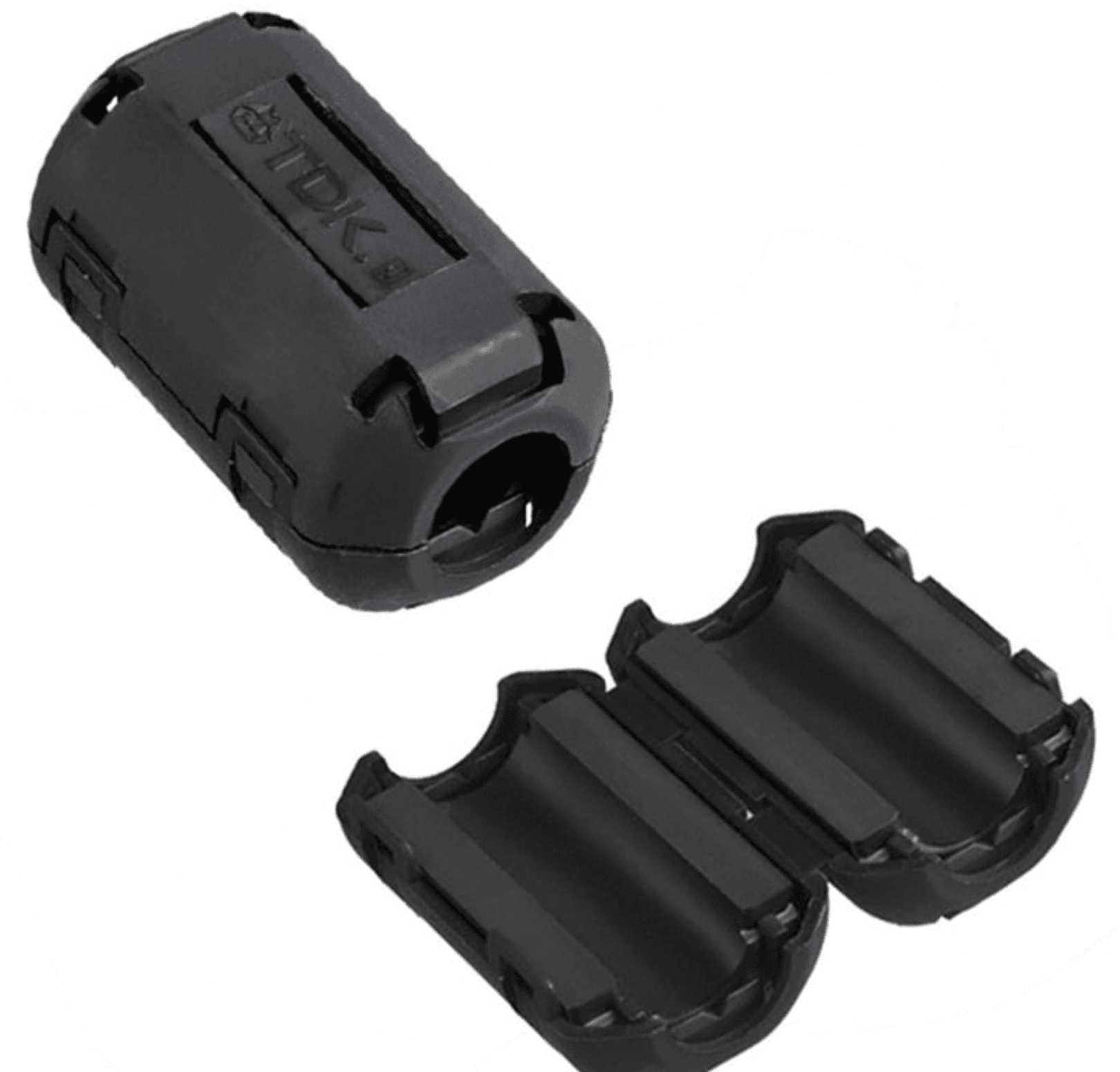
What does a cable ferrite do?
Power and signal cables can provide a path for unwanted high-frequency currents. A cable ferrite adds frequency-dependent impedance to these currents. It is particularly useful for suppressing common-mode interference carried along a cable. Its effect depends on how the selected material behaves at the relevant frequency. [1]
A ferrite does not solve every interruption or connection problem. A dropped data connection, for example, may involve interference, but it may also involve the cable, connector or power supply. Before selecting a part, record when the symptom occurs and which cable is involved.
1. Measure the cable diameter and installation space
Measure the outside diameter of the cable where the ferrite will be fitted. The opening must accommodate it. For a cable bundle, measure the complete bundle passing through the core rather than a single conductor. The housing dimensions and the internal opening are different measurements.
A clip-on ferrite may allow installation without removing a connector. A one-piece ring requires the cable or connector to pass through its opening. Include the closing mechanism, bending clearance and available space inside the equipment in your selection notes. Compare these dimensions against the manufacturer's drawing. [2]
Start by collecting the following information:
- Cable or bundle outside diameter, with a photograph if possible.
- Whether the connector can be removed.
- Available length and width around the intended installation point.
- Whether a one-piece or opening-and-closing construction is required.
2. Match the material to the interference frequency
Two ferrites with the same opening may have different impedance at different frequencies. Do not select a part solely because it fits the cable or is physically larger. Read the impedance-versus-frequency curve together with the frequency range identified by measurement. [1][2]
If the interference frequency is unknown, state that rather than filling in an estimated value as a fact. The equipment type, cable function, power supply and conditions under which the problem appears can guide the assessment. A final choice may require testing several candidates in the same setup.
3. Compare installation positions
Cable routing and its relationship to the enclosure can affect EMC behaviour. Assess the entry and exit points, likely interference source and cable route together. One installation position should not be assumed to suit every device. [2]
Record the baseline before a trial. Then change one variable at a time, such as the ferrite or its position. Keep the cable, load and measurement setup as consistent as possible. This makes it easier to identify which change produced an observed result.
4. Are more turns always better?
Passing the cable through the same core more than once changes the frequency-dependent impedance. The effect is not identical at every frequency. Before adding another pass, check the manufacturer's data, cable bending limits and available opening. [3]
For example, when a connector cannot be removed, first assess the opening and closing clearance of a clip-on part. If there is no room for another pass, narrow the selection around that physical constraint. This is a selection sequence, not a promise that a particular part will reduce interference by a specified amount.
What if the problem remains after fitting a ferrite?
First check whether the problem repeats under the same conditions. Without the exact ferrite model, measurement conditions and tested position, comparing results becomes difficult. Cable routing, shielding and grounding are also part of the EMC system. [2]
Instead of saying only that the ferrite did not work, record which part was tested on which cable and under which conditions. The reverse also applies: one successful trial does not guarantee the same result in another device.
What determines a ferrite core quotation?
A meaningful price comparison requires consistent part definitions. Provide the dimensions, construction, material, manufacturer/model and requested quantity together. Two products with the same general name should not be assumed to be technically identical. Request a current quotation against the complete part description.
What should you send to Artek?
Share the cable type and outside diameter, installation space, interference frequency if known, operating temperature and quantity. Include a photograph or datasheet of the existing ferrite if available. Browse ferrite products or send Artek your application details.
Frequently asked questions
Is a cable ferrite the same as a PCB ferrite bead?
Both can suppress interference, but their mechanical construction and application differ. A core fitted around a cable should not be recommended as a direct replacement for a ferrite bead soldered to a PCB. This guide covers cable-mounted products. [2]
Is the cable diameter enough to select a part?
Diameter narrows the mechanical candidates. Electrical suitability cannot be confirmed without frequency and application information. Describe the device and the observed problem as well as the cable dimensions. [1][2]