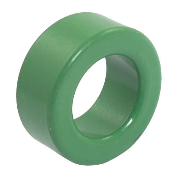
Why does the same shape not mean the same product?
The magnetic behaviour of the material matters as much as the geometry. Ferrite cores and cores made from different powder materials differ in permeability, loss and behaviour under current. Powder cores are themselves a broad group: iron powder, sendust and MPP are not the same material. [1]
Do not describe a sourcing requirement only as a “yellow toroid” or “ring of the same size.” Share the markings, existing manufacturer's identity and application together. A photograph of an unidentified part helps the investigation; it is not a material certificate.
Ferrite and the distributed-gap approach
A ferrite energy-storage design may use an air gap concentrated in a specific region. In powder cores, nonmagnetic regions distributed throughout the material can provide distributed-gap behaviour. These approaches differ in field distribution, approach to saturation and effects around the winding. [1]
This does not mean powder is always better or ferrite is always more efficient. Assess the current at which inductance must be maintained and how losses will be limited under the actual design conditions.
Start the comparison with five questions
These questions define the selection problem before you compare product names:
- What is the inductor's function: energy storage, output filtering or another task?
- At what operating current is the target inductance required?
- What current ripple is added to the DC current, and what is the switching frequency?
- What winding space, outside dimensions and cooling conditions are available?
- Are manufacturer loss, temperature and DC-bias data available?
Without these answers, a material comparison remains disconnected from the real application. Mark unknown values clearly rather than presenting estimates as established facts.
Why examine inductance under DC current separately?
Inductance measured with a small signal may differ from inductance under load current. Magnetic behaviour at the operating point can change the inductance, and saturation and loss limits must be checked. An unloaded AL or inductance value alone is not enough. [1]
When considering a replacement in an existing design, do not assume retaining the turn count will preserve the result. Assess the alternative core's operating-point data together with measurements of the completed inductor.
How should -26 and -52 material codes be read?
Micrometals describes its own Mix 26 material for power-conversion and line-filter applications. For Mix 52, it specifies the same nominal permeability with lower high-frequency losses. This comparison applies to the manufacturer's own materials and test conditions. [2][3]
A similar -26 or -52 suffix in another product name does not establish that it was manufactured by Micrometals or is electrically equivalent. Confirm the actual manufacturer and material documentation of the part being selected.
Compare curves specified at the same frequency, flux density and temperature. Two loss figures measured under different conditions may not show which product is better for the application. [1][2][3]
Can colour identify the material?
Colour can be part of a manufacturer-specific identification system. Without knowing that system and manufacturer, do not infer a definite material from colour. Use the technical datasheet and manufacturer part number to document the identity.
For a quotation, provide a photograph, outside diameter, inside diameter, height and existing markings as well as the colour. Dimensions narrow the geometric candidates; material suitability requires separate assessment.
Example: two candidates have the same dimensions
Suppose two toroids of the same dimensions are available for a design. First verify the manufacturer and material designation of each. Then compare inductance behaviour at the target current, the loss conditions and whether the winding can physically be made. Record the winding, load and measurement setup during sample evaluation.
The choice does not rest solely on which candidate has the higher AL. Look for a candidate that meets the application's requirements and has verifiable data. This is an evaluation sequence, not a performance guarantee for a particular product.
What to include in a toroid enquiry to Artek
Share the outside diameter, inside diameter and height, existing manufacturer/part information, target inductance, operating current, frequency and quantity. Include a photograph of a wound sample if available. Browse iron-powder cores, compare ferrite toroids or send your requirements to Artek.
Frequently asked questions
Can an iron-powder toroid directly replace a ferrite toroid of the same size?
Do not assume a direct replacement. Check the material, inductance, operating current, losses and temperature conditions. Matching geometry does not replace these checks. [1]
Is a higher AL always better?
No. AL is one input to the target inductance and winding decision. It is not a standalone measure of quality or suitability without checking operating-current behaviour, losses and winding space. [1]